Monday 28 November 2016

Week 10 - Relationship Constraints

This week we looked at object relationships and how they can be used to link objects together.

Point constraints

These are a good way to keep a certain distance between objects or to get one object to follow another without animating both. If an object is constrained to two different objects it will calculate the difference between them (see image).


Aim Constraints

I think these types of constraints are the ones I will be using most in my animation if I decide to use them. These allow and object to track another objects movement and 'look' at that object. I set up a quick system where one sphere is following a motion path and the cylinder is tracking that sphere.

One way I will most likely use this is for camera tracking on moving objects, a couple of my scenes in my animation require the camera to track a ships movement, this is a perfect way to do just that.

Monday 21 November 2016

Week 9 - Rigging And Skinning

This week we learnt how to rig models with skeletons and manipulate them using joints.

First step was to make the joints of the skeleton and align them with the hand, this is so they can be manipulated and controlled later


After this I used the interactive bind tool to make sure that no volume was extended more than required.


After this all that needed to be done waws to bind the skeleton to the model and then manipulate the joints. The main problem I faced during this was the model losing shape during joint manipulation, i think this was mainly due to me not editing the bind heat maps very well. I may use this technique in my x-wing model for the animation of the wings but we will see when the time comes.

Tuesday 15 November 2016

Week 8 - Motion Pathing

Motion pathing is a great way for objects to follow a pr-set path or for use a a make shift camera dolly.

This week we learnt about motion pathing by making our models follow a pre-drawn path. One of the difficulties I found with this tool was that you had to make very smooth lines in order for the movement to look realistic. Also it is hard to change the objects rotation and scale mid way through the path as this stops the animation. I tried adding a keyframe for the U value of the motion path but this didn't seem to change the objects position.

A major problem that I had with motion pathing was that every time I tried to edit the motion path after an object was attacked to it, Maya crashed, it seems like this is a problem with this version of Maya but luckily there was a fix for it by changing the evaluation type to DG from parallel then changing it back when you are done editing the path.

Week 8 - Bouncing ball Animation

This week we learnt about keyframing and animation.

In this practical we were tasked with creating a bouncing ball animation using a schematic as reference. This was easier than I thought it would be and taught me some useful techniques when creating my star wars animation such as key framing and how to use the graph to manipulate certain aspects of the object.

Downfalls/Useful Tools

One of the hard things about this task was keeping the objects shape throughout each frame when I changed the shape in 2 frames after it seemed to change the shape of the first frame too. To fix this I found that the graph editor was very useful, It helps give a smooth animation and helps to visualise what the actual animation is doing.

Monday 14 November 2016

Week 7 - Skydome

This week we learnt about lighting and camera movements as well as how to add detail lto our scene using skydomes.

Skydome

For this weeks practical we had to create a skydome. This is basically the sky for your scene and is created by adding a texture to a dome.


This is a really useful tool for adding depth to your scene and making it feel more real rather than having no background. I will be using this technique when I come to make my animation and will replaye the clouds with a space texture.


One problem I had when creating this was that when I imported the picture onto the material, it also imported it onto the transparency layer as well as the colour layer. This meant that my dome was transparent. To fix this i had to break the connection between the material and the transparency layer in the hypershade window.

Friday 11 November 2016

Blog/model Reviews

Blog 1

One good thing about Rayhans blog is that it is very detailed and clear to understand, new techniques are highlighted in bold like in my blog. The main problem I have found with his blog is that although the sections for the blog are split into each week, there tends to be too much all in one post, it may have been easier and clearer for other people to find what they are looking for if he split it up into separate posts for each section e.g. 1 post for a practical and another for making the model, post a new enrty as you go through each section. Saying this, I like how Rayhan has each of the class practicals shown step by step where as mine just shows the finished product at the end and a breakdown of what I learned, looking back it may have been better to show the process of each practical and reviewing it as I went along.

The models themselves were good detail and fit his schematics well, the only thing I would have said is that it might have been better if he included a picture of the finished model at the end rather than just the modelling process. I like the way he has reviewed his models at the end of the blog in a clear bullet point list, I decided to review my models as I was talking about them but it might have been easier or clearer to discuss them in a list at the end.

Blog 2

I like how Daniels posts are split into sections as he was working on each part, this makes it easy to view a specific section using the menu on the side. The models themselves are well detailed however it would have been nicer to see text highlighted bold where new techniques were used. Again, like with Rayhans blog, Daniel included more detail on the class practicals and how he actually made the models for them, this is something I feel I could have done more of in my blog.

Wednesday 9 November 2016

Dreadnaught - Modelling Process

I decided to change my model from the phoenix home to the Dreadnaught as there were no schematics that I could find for the phoenix home, the storyboard still remains the same however.

Basic Shape

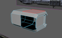
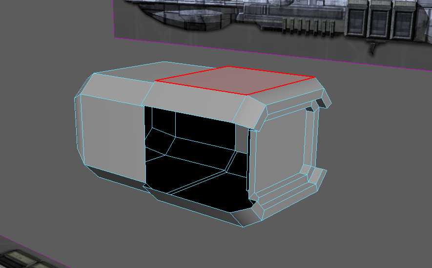
As with the other models I started with the basic shape, with this model I found it hard to find schematics and had to resize the images to fit and align correctly. I did this with multiple edge loops and extrusions

The main problem I had was trying to get the rounded shape for the bottom as I was using a cube to start with, in the end I added more edge loops to create a rounded effect. What I also found hard was trying to figure out the size of the rounded edge from the front schematic as it wasn't a very basic schematic. I tried to find an easier one to work with but this was the best I could find.

Engine

The engine was quite a simple design and was achieved with extrusions with beveled edges. Once one engine was done I just needed to duplicate it and move it to the right place.


I made a mistake on this bit at first and by the time I realised it was too late to undo, in the reference I was working on the engine only had a cover on the top and bottom half where I put a cover all around the engine. To fix this I deleted the side faces and then bridged and filled hole to fill in the gaps, then used the multi-cut tool to create the edges again.

Ship Details

I created the outer braces and windows of the ship based on the schematics with extrusions and bevels again.

Outer Details

After this I created an antenna and some bulbs for the outer decor. For the antenna I created a cylinder base then reduced the subdivision axis to make it more octagonal, i then extruded the centre upwards and moulded the vertex into shape based on the schematic, After this I created the antenna dish by cutting a sphere in half and extruding the faces.

(I'm not a fan of the bulbs on the outside of the ship but that's what it has in the models I've seen)

Overview

Overall I feel like I need to add more detail to this ship but from the references I've seen, most of the other details are added with textures rather than moulded on the ship itself. One thing I would like to improve on is the shape of some of the edges of my ship, parts are a bit jagged and aren't quite smooth, I wanted to use a similar method I used for the X-Wing but because there were a lot of edges and uneven surfaces it was hard to add edge loops and smooth the surface.


Dreadnaught Class Heavy Cruiser - Moveboard

This is the moveboard I will use to make my dreadnaught, there aren't too many images I could find for this ship but these are the ones I managed to get:


The main reference I will be using is the top left image.

Saturday 5 November 2016

TIE Fighter - Making the model

Basic Shape

I started off the TIE Fighter by creating a sphere and moulding the basic shape by cutting out edges by selecting edges and deleting the edge and vertex, this gave me a hexagon shape that I wanted for the window and back. I then extruding them inwards, I started at the front, then made the back in the same way. I then split the model in half so I could work on one side and duplicate it to the other side later. For the start of the arms I used more extrusions and vertex manipulation.
 
The main problem with this was trying to make straight edges and manipulate the shape while still keeping the spherical shape of the body, in hindsight I could have used a separate object for the brace on the side but at the time it worked and didn't turn out bad in the end, i make come back to it and change it later.

The Connector/Brace

After the body I Started to create the connector that connects the wing with the cockpit, I did this in a similar way to the gun on my X-Wing, lots of extrusions. I also used the same technique of duplicating the cylinder selecting faces, inversing and extruding to make the brace between the connector and the wing. I found the Freeze Transform tool useful here as it allowed me to work on my model elsewhere and then perfectly align it back again by setting the transformation back to 0.

The Wing

The Next step was to make the wings, This was relativity simple and just required some extrusions and vertex manipulation. I will most likely come back to the centre part of the wing to add more detail with bump mapping when I add textures.

Connecting/Mirroring the object

Now that the basic shape is completed I decided to mirror the object to the other side by grouping the objects, changing the pivot point to the centre of the split and then changing the x scale to negative. I then had to combine each sides objects and merge the vertexes together. This meant that the shape was easier to manage and there were less vertices to worry about.

The Guns/Top of the body

For the guns I created a cube with some cylinders, shaped the vertexes and extruded the shape to look like the ones on my reference images from the moveboard. I then tried creating a top bit for my model by duplicating it, selecting the faces I needed and then inverting the selection and deleting the bottom half. This looked ok but it wasn't quite what I wanted so instead I decided to extrude the top face and got a nicer effect.

The Engine

I was going to do this in the same way as I did the X-Wing engine where I created an object, changed the pivot point to the centre then duplicated and rotated it around but instead I decided to extrude the engine inwards instead in a hexagon pattern as this is what it looked like in the reference images I have looked at.

Overview

Overall the model is very basic but that is because I wanted to add more detail when I come to texture it, I may add more detail to the wings and body later but for now I want to try and get a nice effect when texturing using bump mapping and other tools.

TIE Fighter Moveboard

This is the moveboard of images I collected for reference when making my TIE fighter:


I chose these at it shows every angle of the TIE fighter so I will have plenty of reference.

Thursday 3 November 2016

Week 6 - Materials Part 3

This Week we learned about the UV editor and how you can manipulate textures around an object.

UV Editor
This is a really helpful tool if your imported texture doesn't quite match up with your model and you want a more accurate manual way of aligning a texture. I will most likely be using this when creating my star wars textures as it will allow me to model textures around objects more accurately.

Wednesday 2 November 2016

Week 6 - Materials Part 2

This week was more on materials and fixing the problem we had last week with the image not wrapping properly to certain objects.

Projection Mapping

This is a really good way to apply textures to an object and they will wrap around the object based on what shape it is. This is going to be very useful when I am adding textures to my models as it will make sure that the texture fits correctly.


Planar Mapping
I also tried out using a Planar mapping on the sphere and got an interesting result, It seemed to map the texture straight onto the object instead of wrapping around, I preferred this setting to the spherical wrapping but on most spherical models you want to texture to wrap all the way round and not cut off. I will be playing about with them more when I come to texture my models and see which one fits bets to each object.


Mapping Manipulation
I tried out changing the size of the projection using a cube and got some interesting results, I noticed the texture wrapped around the object and stretched to fit the edges, This could be useful but could also hinder me when texturing my models as it could make the object look distorted.

New Techniques Learnt

Helpful tools/Shortcuts
Most of these I learnt when creating my X-Wing model:

Delete Edge Vertex - Deletes edge along with the vertex, This helped a lot when I was creating edge loops for the ship
Drag select faces - I mentioned this in an earlier post but this tool is very useful for selecting multiple faces quickly and I used it a lot in my models as it saved me time.
Shift + period - to increase selection by 1 region, I used this when modelling the detail on the engine, I selected the top faces and needed the sides as well so I found this shortcut to help speed things up.
Inverse selection - I used this quite a bit mainly to cut out the detail on my engines, it is very useful as it saves me selecting all the opposite faces which would have taken me longer.
Freeze Transformations - For when I duplicated objects and wanted to make extra details like on my engine, freeze the transformation, work on the objects away from the other one then set the axis to 0 again to perfectly align it back.
G to repeat previous actions - I used this quite a bit when i was smoothing out my objects, it saved me time rather than trying to find the tool in the menu.

A Technique I found but did not use

Append to polygon - This creates a polygon between two edges and the reason I didn't use this is because I prefer the bridge and fill hole tool however I can see how this tool can be useful as you can just click the edges instead of going into the menu and selecting bridge.

X-Wing Part 3 - Adding More Detail

In this part I will be adding more detail to the model and be trying to add the finishing touches.

The Gun

This was part was pretty simple, just shaping a cylinder with lots of extrusions. A few techniques I used while modelling it were cutting the cylinder of the gun in half and using the bridge tool to create the C shape.

Wings Cont.

For this I grouped the wing objects changed the wings pivot point to the centre of the ship and then duplicated the object so I had 4 wings. A shortcut I found really helpful here was when you select any object from a group and press the Up arrow, it selects to group that object is attached to.

Details

For this part I cut out holes in the back and side of the sip to add room for the wings to extrude into the ship. I also added some random objects to the top and back and an R2-D2 on the top of the ship to make it look more detailed. I may change these to textures later on to improve polygon efficiency but for now it looks good.

Overview

Overall I think the model creating process went pretty well, the main problem I had was when I was smoothing my objects, every time I smoothed an object it lost it's shape or was slightly out of line with another object, to get around this I used edge loops around the corners and sharp edges so the objects kept their shape however this meant that I had a lot of edge loops in my model and it made it look slightly untidy.

Tuesday 1 November 2016

X-Wing Part 2 - Getting Started

Basic Shape (Main Body)

The first thing I wanted to do when making this model was to get the basic shape done. I started with a cube and sized it to fit the schematics by editing the vertices, faces and edge loops. I then extruded upwards for the front window. I also found that changing the transform constraints to 'Edge' made it a lot easier to move edges/vertices without distorting the model.


Window

For this part I used the edge loop tool (which I use a lot later on) to create the window frames and then extruded the windows inwards.
I then used the smoothe tool to make the window and body look better as they both looked a bit jagged. The problem I had with this is that when it smoothed it rounded the objects too much. To get around this I put in edge loops around the sharp edges. This made the object look more defined and rounded while still retaining the sharp edges. I then extracted the objects of the window to make my scene more neat with the layers.

Front Nose

For the front nose I started by making the basic outline using a cylinder and editing the vertexes. I then used another cylinder and used the difference boolean to create a cut out section of the nose.

I then extruded the front part inwards and extracted and enlarged the back part of the shape to make it slightly bigger than the front part so it looks like a brace based on one of my reference images. I also created divisions on the front part of the nose and extruded them inwards to give it more shape and detail.

Wings

For this part it was more extracting with some boolean difference to cut out a shape for the fan. 
I used the inverse selections and the dragging select tool to model the details of the engine cover. At this point I also realised that I was using the edge loop tool a lot so I added the shortcut to my hotbar for easy access.

Fan/Engine

The next step was to add detail to the fan. To create the propeller I selected I selected the two edges inside and used the bridge tool to create a bridge across the middle. For the outside of the fan I just moulded the vertexes of a cylinder to create the right shape and then duplicated and cut the fan in half and smoothed the top half to make a cover.
To make the pattern on the outside of the shape I duplicated the fan cover, smoothed the object so i had more polygons to work with and then drew out a pattern on the faces based on a reference image in my moveboard. I then inversed the selection and deleted the bits that weren't part of the pattern. After this I positioned the pattern into place, changed the pivot point to the centre of the fan, duplicated the object and changed the x scale to negative so the pattern was replicated on both sides.
For the back engine I created it in a similar way, more edge loops, extruding and vertex moulding.
One shortcut I found useful when modelling the back engine was Shift + D, this allowed me to easily create the detail for inside the engine and the cover outside the engine by moving the pivot point to the centre of the engine, duplicating it and moving/rotating the object the same way. F to frame the object was also a useful tool.

X-Wing Modelling - Moveboard/Schematics

These are the reference images I will use to model my ship off of:


I tried to get the model from all different angles so I could easily reference it when designing. I also found a simple schematics drawing to use as reference, I wanted to keep it simple as it is easier to model off of. I then imported the images into Maya to make a box shape.